-
Notifications
You must be signed in to change notification settings - Fork 2
5. Breadboard setup PNP
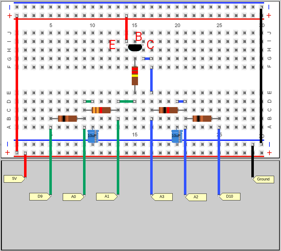
Use this wiring diagram to make IV traces of PNP transistors.
I have inserted a 220k resistor between the base of the transistor and the filtered signal from D9. You will need this resistor when testing transistors with a high gain. Most modern small signal transistors will have a very high gain.
Note that I have marked the emitter (E,) base (B,) and collector (C) of the transistor. You will have to check how your transistor is wired. There are several different pin arrangements for transistors. You must look up the datasheet of your transistor and match the emitter, collector, and base connections to the positions shown in the diagram.
Note that the emitter is connected to the 5 volt power supply. This is different from the NPN transistor setup.
