-
Notifications
You must be signed in to change notification settings - Fork 430
P330 Battery Intelligent board
Function
Variants
Parts
Programming
External interfaces
Service interfaces
Board view
Schematics
DJI Intelligent Flight Battery for P2 is a 5600mAh, 11.1V LiPo 3S battery, supporting up to 25 minutes of flight time. The battery also has built-in sensors and LEDs that let you know the status and remaining power.
The battery management system chip communicates with Naza Flight Controller using Smart Battery System protocol protocol, specifically SBS Data V1.1 protocol.
The SBS protocol defines battery-related commands to be transferred over SMBus, which in turn is deviced from I2C.
There are multiple versions of the board.
| Marking | Overview |
|---|---|
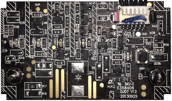
| DJI07 V12 20130929 | |
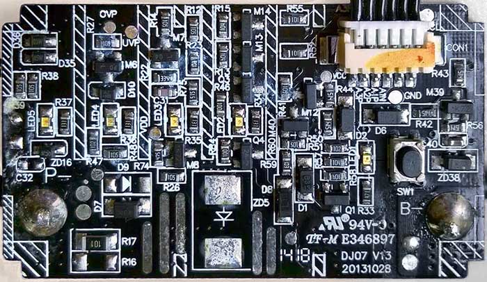
| DJI07 V13 20131028 |
| Marking | Amt. | Pkg. | Function | Specification |
|---|---|---|---|---|
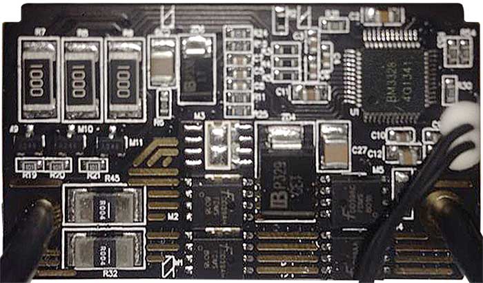
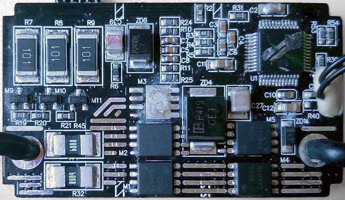
| BM3328 | 1 | LQFP-48 7x7mm | BMTPow BM3328, 2-4 Cells Lithium Battery Gas Gauge Management and Protection IC | datasheet |
| TPS1AH FDMS | 4 | N-channel power MOSFET; markings uncertain |
| Chips | Firmware | Description |
|---|---|---|
| unknown | m1100 |
Connectors on the board are:
| Marking | Overview |
|---|---|
| P- High Current Soldering Pads | Power output wire of the battery |
| B- High Current Soldering Pads | Battery cells connection |
| TS Soldering Pads | Temperature sensor connection |
| 6-pin Balancer and comms con. | Contains connections for cells balancing, plus wires for the communication interface connected to Naza FC. |
Here is the connector pinout:
| Pin | Label | Function |
|---|---|---|
| 1 | ? | |
| 2 | ? | |
| 3 | ? | |
| 4 | ? | |
| 5 | ? | |
| 6 | ? |
The following service pads exist on this board:
| Marking | Overview |
|---|---|
| TODO |
Top of a DJI07 V12 board:
Bottom of the DJI07 V12 board:
Top of another DJI07 V13 board:
Bottom of the DJI07 V13 board:
flowchart LR
    Connector-BAT((batt<br/>connec<br/>tor))
    subgraph Battery Intelligent board
    direction LR
    BatteryBMS[BM3318 BMS<br/>Lithium pack<br/>manager]
    BattFeedbackR(0.02 Ohm<br/>feedback<br/>resistor)
    BatteryButton(button)
    BatteryLEDs(LED line)
    BatteryBMS---BatteryButton
    BatteryBMS---BatteryLEDs
    ChargeDischargeFET(MOSFET<br/>charge<br/>discharge<br/>control)
    BattFeedbackR===ChargeDischargeFET
    BatteryBMS---ChargeDischargeFET
    end
    subgraph Li-Po cells pack
    direction TB
    BatteryCell1(battery<br/>cell 1)
    BatteryCell2(battery<br/>cell 2)
    BatteryCell3(battery<br/>cell 3)
    BatteryTempSense(thermistor)
    BatteryCell1===BatteryCell2
    BatteryCell3===BatteryCell2
    end
    ChargeDischargeFET===BatteryCell1
    Connector-BAT== PACK- ===BattFeedbackR
    BatteryBMS-- VSS ---BatteryCell1
    BatteryBMS---BatteryCell2
    BatteryBMS---BatteryCell3
    BatteryBMS-- SR ---BattFeedbackR
    BatteryBMS-- TS ---BatteryTempSense
    Connector-BAT== PACK+ ===BatteryCell3
    Connector-BAT-- SMBus ---BatteryBMS
Thick lines are the ones transferring high power. Feedback resistor for measuring current, as well as all MOSFET switchesm are inserted into negative line. The three Li-Po cells are connected in series, so that the voltage sums up.
The Battery Management System chip communicates with FC using the protocol described in Smart Battery Specification, over SMBus interface. It is uncertain whether there are any DJI-specific extensions to the protocol. The charge level, as well as errors spotted by the BMS, can be shown on attached line of four LEDs. The BMS can also read button state, and based on that, start or shutdown the power delivery.
No schematics available.
This page is created by drone enthusiasts for drone enthusiasts.
If you see a mistake, or you know more about specific subject, or you see an area for improvement for the wiki - create an issue in this project and attach your patch (or describe the change you propose).


