-
Notifications
You must be signed in to change notification settings - Fork 2
Getting Started
This tutorial aims to get you started with VERA using a simple project. The project will allow you to (1) Coregister MRI and CT, (2) define the number and type of electrodes implanted, (3) create a 3D model of the cortical surface, (4) localize the implanted electrodes, (5) export the electrode locations as a PowerPoint, and (6) create a MATLAB export for further analysis.
- Component A Component refers to a contained processing stage. For example, aligning CT and MRI images or determining the electrode locations.
- Pipeline The pipeline is a series of Components for a VERA project.
The core of VERAs architecture is its modularity. To achieve the goals of this tutorial, you will have to install additional software packages for specific functions.
VERA is a toolbox written entirely in MATLAB, and you will need a MATLAB installation with MATLAB R2018b or higher. Some VERA Components require additional MATLAB toolboxes to be installed. We recommend installing the "Image Processing Toolbox", "Statistics and Machine Learning Toolbox", "MATLAB Report Generator Toolbox", and the "Computer Vision Toolbox."
You can download the VERA code directly from the Github Repository.
While the specific dependencies depend on the pipeline, the following tools will be sufficient for most use cases. Please follow the instructions from the respective tools.
Freesurfer will allow us to reconstruct the cortical surface and label cortical and subcortical structures. Note that if you want to install Freesurfer on windows, you will need to do this via WSL. An easy way to accomplish this is to use Freesurfer4Windows. If freesurfer is used via windows, you will have to add the WSL path pointing to your mounted windows drives into VERA (UbuntuSubsystemPath). The default value if you are using Freesurfer4Windows should be /mnt/
Make sure to copy a freesurfer license into the freesurfer folder! Freesurfer will not run without a license file present. You can get a freesurfer license here.
SPM12 is a well-supported, widely used neuroimaging tool we will use for coregistration. Be sure to specify the operating system and MATLAB version you would like to use SPM12 for, as this may affect what is downloaded. Consider using the developer version of SPM12, as this standard version distributed on their web page is not compatible with macOS Sonoma or with MATLAB 2024a and above.
The ReportGenerator is a small tool developed in our lab to produce easy-to-read information about implanted electrodes.
Now that all the surrounding tools are installed, it is time to start VERA. Run **startup_VERA.m ** from the VERA root directory. To create a new project, click in the Menu on File -> New Project. Now, create a new folder for your subject, and choose the appropriate pipeline. For this tutorial, we created a Pipeline called SimpleTutorialPipeline. If you want to add your pipeline definitions to the available list, copy them into the PipelineDefinitions folder in the VERA root directory. VERA will initialize the folder with VERAs project structure and load the project view.
This is how VERA should look after creating the project.
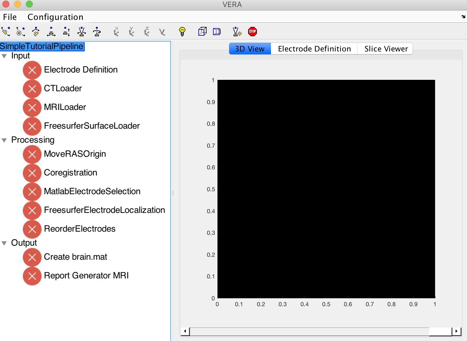
Assuming that this is the first time you are running VERA, you will have to tell VERA how to resolve the dependencies to Freesurfer, SPM12 and if you are on Windows using WSL, to the WSL root directory. Open the settings window under Configuration->Settings.

These configurations will be stored, and you will only have to add them the first time you use VERA. Due to the nature of VERA, dependencies will only show up after loading a project as each project can have different dependencies. You can now click on the three dots next to the dependence and select the SPM12 and Freesurfer root directories. If you are using WSL, you will have to specify the point for the windows drives (if you used Freesufer4Windows, it should be set to /mnt/).
You can now press Configuration-> Configure all Components, which will initialize the components. VERA should look now like this:
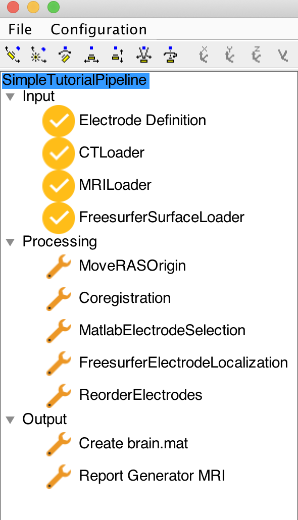
The tree structure on the left-hand side of the GUI represents the different steps to be completed. Internally, VERA will ensure that a Component can only be used if all the required data exists. VERA will indicate the status of a Component with the icon next to the component name.
![]() This icon indicates that the Component is ready. You can either right-click on the Component and select run or select the Component and choose run in the Menu item corresponding to the name of the Component.
This icon indicates that the Component is ready. You can either right-click on the Component and select run or select the Component and choose run in the Menu item corresponding to the name of the Component.
![]() The wrench indicates that the component is configured, but upstream data (i.e., the output from another component is missing).
The wrench indicates that the component is configured, but upstream data (i.e., the output from another component is missing).
![]() This task is completed and no more actions are required
This task is completed and no more actions are required
Here we will guide you through running the localization, step by step, explaining each Component. In this project, you now have four components that can be executed, indicated by the item next to their name. Each Component can be started by right-clicking -> run or through the Menu on top after selection.
As a first step, we need to define some information about the implanted electrodes. Following components can use this information. Run the Electrode Definition component (right-click->Run). A new window will open up, allowing you to enter electrode definitions.

VERA currently supports definitions for Grids, Strips, Depth, and DBS electrodes. You will need to specify a name, the number of contacts, the spacing (center to center), and the contact volume for each defined electrode. A typical electrode volume for SEEG electrodes is around 30mm^3.
To add a new definition, press the Add button on the lower right, a new line will appear. If you want to delete a definition, select it using the checkbox on the left to the definition and press delete.
Side Note: If you are using a ROSA robot for implantation, VERA offers the possibility to import ROSA trajectories through the ImportROSFile component, reducing the effort for electrode localization significantly.
Here is an example of a finished entry for the electrode definition:

After you have entered the definitions, you can close the window. You can inspect the electrode definition by switching to the right panel's Electrode Definition view tab.
The following two Components (MRILoader, CTLoader) will load the MRI and CT. After clicking run, a selection window will open up, prompting to select the files accordingly. At this time, VERA accepts NiFti and DICOM files (choose any file from the sequence). If the DICOM contains data from multiple volumes, you will be prompted to choose the correct DICOM from a list.
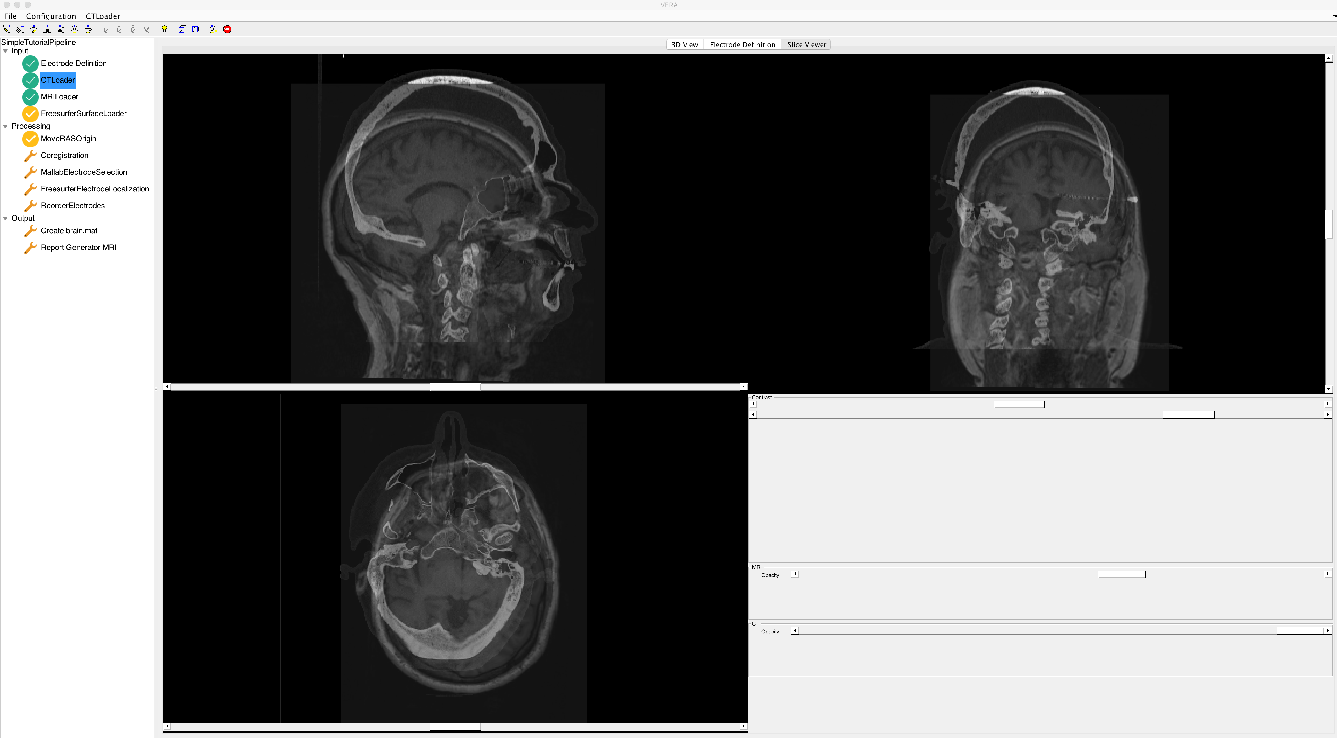
You can inspect the images by selecting the Slice Viewer on the right. The Slice Viewer allows you to change the image contrast and opacity for each image.
VERA should look like this after importing both MRI and CT. As you can see, MRI and CT need to be coregistered. Coregistration is part of the VERA pipeline and will be done later.
This Component allows you to load an already existing Freesurfer segmentation. Loading a Freesurfer segmentation includes cortical surfaces from both hemispheres, the standard ASEG subcortical segmentation, and the spherical coordinates. Please ensure that the MRI used for the segmentation is the same as the one you loaded in the previous step, as all data will be projected into the MRI RAS space, and it is assumed that MRI and 3D model is in the same space. Press run and select the Freesurfer project folder for the subject to load the segmentation. It is also possible to run the Freesurfer segmentation within VERA using the FreesurferModelGeneration Component.
You can now see the labeled 3D surface in the 3D view on the right.

Now that all the Inputs are defined, we can move on to process or data. The only Component ready to be executed in your pipeline is MoveRASOrigin. This Component recentered the CT to closer overlap with the MRI. This is necessary because sometimes, the coordinate system differences between CT and MRI make it impossible for SPM12s coregistration algorithm to converge.
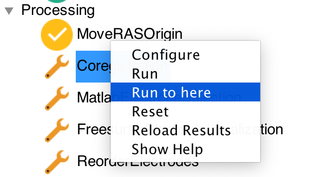
In this step, we could press right-click on MoveRASOrigin and then run on Coregistration (which uses SPM12 to coregister CT and MRI). A faster way is to right-click the Coregistration component and press "Run to here". This action will prompt VERA to run all Components necessary to run the Coregistration. In our case, this will first run MoveRASOrigin and, after that, launch the Coregistration.
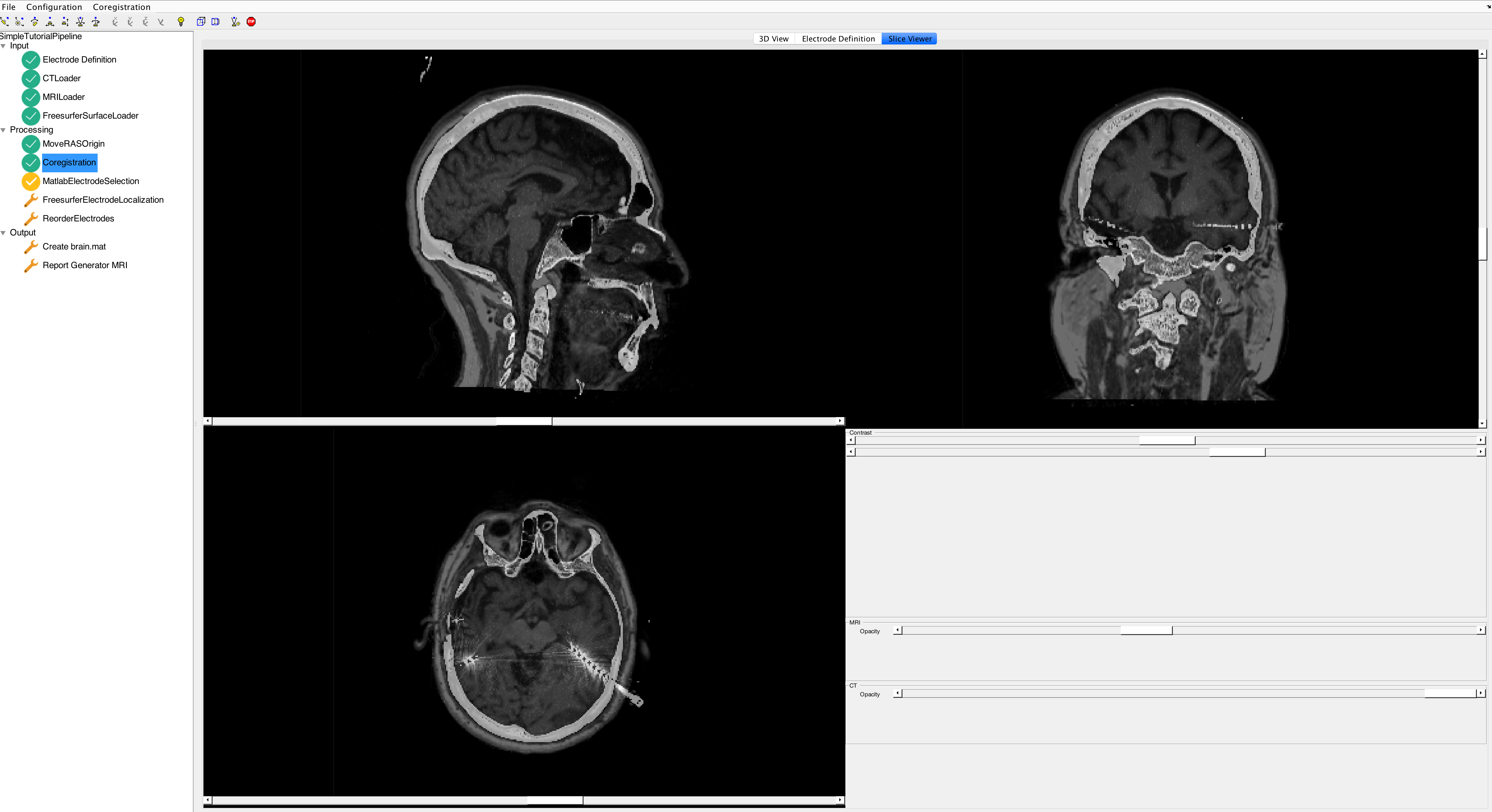
You can check the results of the registration in the Slice Viewer.
Next, we want to find each electrode's exact X, Y, and Z coordinates and assign it to a specific SEEG shank. For this purpose, we create the MatlabElectrodeSelection GUI. After running the GUI, you can see electrode definitions on the left and the 3D surface on the left. In addition, the red dots represent potential electrodes as determined by a thresholded CT. The threshold can be changed with the upper scrollbar at the bottom. The scrollbar below will change the opacity of the 3D model. Using the ROSA trajectory import, the GUI will show the trajectories and enable you to use the automated localization in the Menu on the top left.
On the top of the window, you can see MATLABs camera toolbar, which you can use to manipulate the brain with overlapped electrode locations. Once you put the 3D image into an optimal angle, deselect the toolbar (a second click on the selected toolbar item will unselect it).
To add locations to a specific definition, select the definition (In brackets, you can see the number of associated electrodes and the total number of expected locations) and then click on the location you want to associate with the definition. If an electrode is a grey, it is already associated with another definition. Click the location again to remove the association.
Alternatively, you can take advantage of the automated localization functionality. Select a non-edge electrode then right-click the definition and select "find all connected locations".

It can sometimes happen that the Matlab localization cannot find all locations or find more than the expected number of locations. This can have multiple reasons. The tool will identify the shank-screws as electrodes. This will cause an additional electrode to appear. Similarly, if electrodes are close to the shank screw, they appear as a single location. Sometimes, electrodes outside the cortex will not be connected to the clinical system - they will appear in the imaging, but you might not want to add them in VERA. Some locations outside of the brain stem from wires and cables; they can be ignored as they are just artifacts.
After successful localization, you can close the window. If you want to change any locations, you can always rerun this Component.
We use this Component to verify that all electrode locations are correct manually. For this purpose, we will open up Freesurfers Freeview. Here is a short tutorial on Freeview. If you run the Component, VERA will open Freeview, load the CT and import the electrode locations. If you also have trajectories, additional point sets for the trajectories will be added as well.

As a first pass, to check if all electrodes are roughly at the correct location, select all point sets on the left side and increase their size (Radius) to 2. Next, you can create a 3D view from the CT. To enable this, select the CT, and enable "Show as isosurface in 3D view". Now adjust the low and high threshold until the electrodes are segmented correctly.
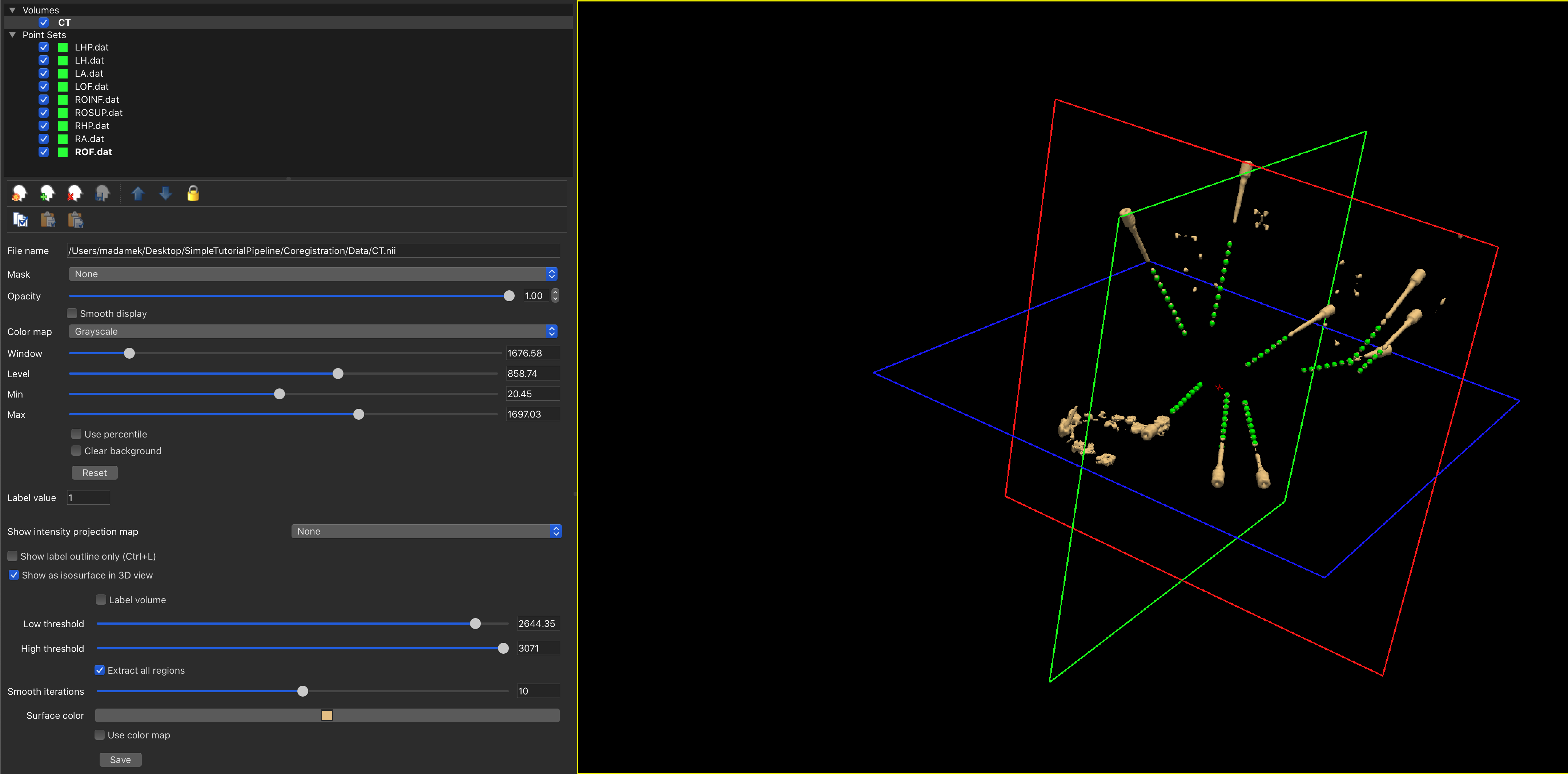
If you need to edit the points of a definition, you can select the Point-Set and use Freeview's edit button (![]() ). Editing allows you to drag around buttons, create new points with a left-click or delete points using a shift-left click.
). Editing allows you to drag around buttons, create new points with a left-click or delete points using a shift-left click.
Don't forget to save all your changes before you close Freeview!.
NOTE: If you run the FreesurferElectrodeSelection a second time, it will ask you to keep or override changes. Override will remove all changes made in Freeview and reload the Locations defined by MatlabElectrodeSelection.
The last step is to ensure the electrodes are in the correct order, corresponding to the channel labels they receive. For example, the first electrode of an SEEG electrode is most proximal. The ReorderElectrodes Component allows you to reorder the contacts and the definitions, to best reflect the order of the electrodes.
On the left, you can see all the electrode definitions, using shift, you can select multiple definitions and their numbering on the brain. The up and down buttons next to the list can be used to change the order of the definitions, which will change the electrode numbering relative to the other definitions. By default, electrode locations will be shown in the "Clinical Numbering Scheme, " which individually handles each electrode. If you switch to the "Research numbering scheme," you can see increases similar to the channel numbers.

If you need to resort to a channel, you can either try the automatic version (by selecting the channels you want to resort to) or press the Auto-Sort button. Otherwise, you can manually resort to the indices by selecting one definition and pressing the Re-sort indices button. This will open up a new window where you can click on each electrode to assign it a number in increasing order. If you made a mistake, you could right-click to remove the assignment.
The last section of VERA is output. Outputs do not alter data within the pipeline but are meant to export into different formats or generate reports. Outputs can be created at any stage of VERA, so an Output could be available although not all Processing components have been executed.
For today, we have two output components. The first Component will use the electrode locations and the 3D model as a MATLAB mat file for external use. The second Component will allow you to create a project structure that our ReportGenerator can use.
Running the ReportGenerator Component will open up the report generator. Watch this video to understand how to use the report generator. After creating the report has finished, close the ReportGenerator GUI and you will be prompted with a window to ask where to store the report.
- Introduction
- Getting Started
- Pipeline Tutorials
- Pipeline Designer
- Project Directory Specifications
- Understanding the Pipeline Workflow File
- Components
- AlterElectrodeLabels
- ApplyMask
- CalculateDistanceToSurfaceLabel
- CalculateDistanceToVolumeLabel
- CascadeInput
- CombineLocations
- Copy
- EEGElectrodeNames
- ElectrodeDefinitionConfiguration
- ElectrodeTransformation
- EstimatePositionFromTrajectory
- FileLoader
- FlipVolume
- ImportROSFile
- LabelVolume2Surface
- MatlabElectrodeSelection
- MatOutput
- MatOutputLegacy
- MatOutputNoElectrodes
- MoveRASOrigin
- MoveRASOrigin2Volume
- NiiOutput
- ObjOutput
- ReorderElectrodes
- ReplaceLabels
- ReportGenerator
- SphericalTemplateProjection
- SurfaceTransformation
- TalairachProjection
- FreesurferDatExport
- FreesurferDeface
- FreesurferElectrodeLocalization
- FreesurferHemisphereLoader
- FreesurferHippocampalSegmentation
- FreesurferModelGeneration
- FreesurferSurfaceLoader
- FreesurferThalamusSegmentation
- FSDicomImport
- ImportFreesurferSegmentation
- LoadFreesurferSegmentationVolume
- LoadFreeviewPointFile
- LoadFSMNIProjection
- YeoParcellation


