-
Notifications
You must be signed in to change notification settings - Fork 1
Detection_Methods.md
- Detect opponent vehicles within 2 meters but no less than 30cm.
- Opponent can be anywhere between 9 and 3 o'clock relative to the vehicle.
- Determine the opponent's position with a 5cm maximum deviation.
- Determine the opponent's orientation with 25° precision.
- Processing time should be less than 300ms.
Several methods were researched to meet the above requirements, including:
- LIDAR: Provides high precision and range but may be costly.
- Ultrasonic Sensors: Cost-effective but less precise.
- Camera-based Systems: Versatile and can provide orientation data.
LIDAR systems offer high precision and range, making them suitable for detecting opponent vehicles. They are already integrated into the original F1tenth platform, providing reliable distance measurements.
Ultrasonic sensors are a cost-effective solution but are less precise compared to LIDAR and camera systems. They might not provide the required accuracy and precision for our specific needs.
Camera-based systems provide a versatile solution capable of capturing detailed information about the opponent's position and orientation. They offer high resolution and can be used for both distance measurement and orientation determination.
After evaluating various methods, the following were selected:
- LIDAR for precise distance measurement (already part of the F1tenth platform).
- Camera-based System for orientation determination and additional positional data.
This project implements two detection methods. We call the first method Gradient Merge & Centroid Detection and the second method is based on detecting AprilTags.
-
Advantages:
- Fast processing.
- No AprilTag needed.
- Utilizes LIDAR sensor.
-
Disadvantages:
- Can not detect if the vehicle is not present.
- Can not estimate the heading of the vehicle.
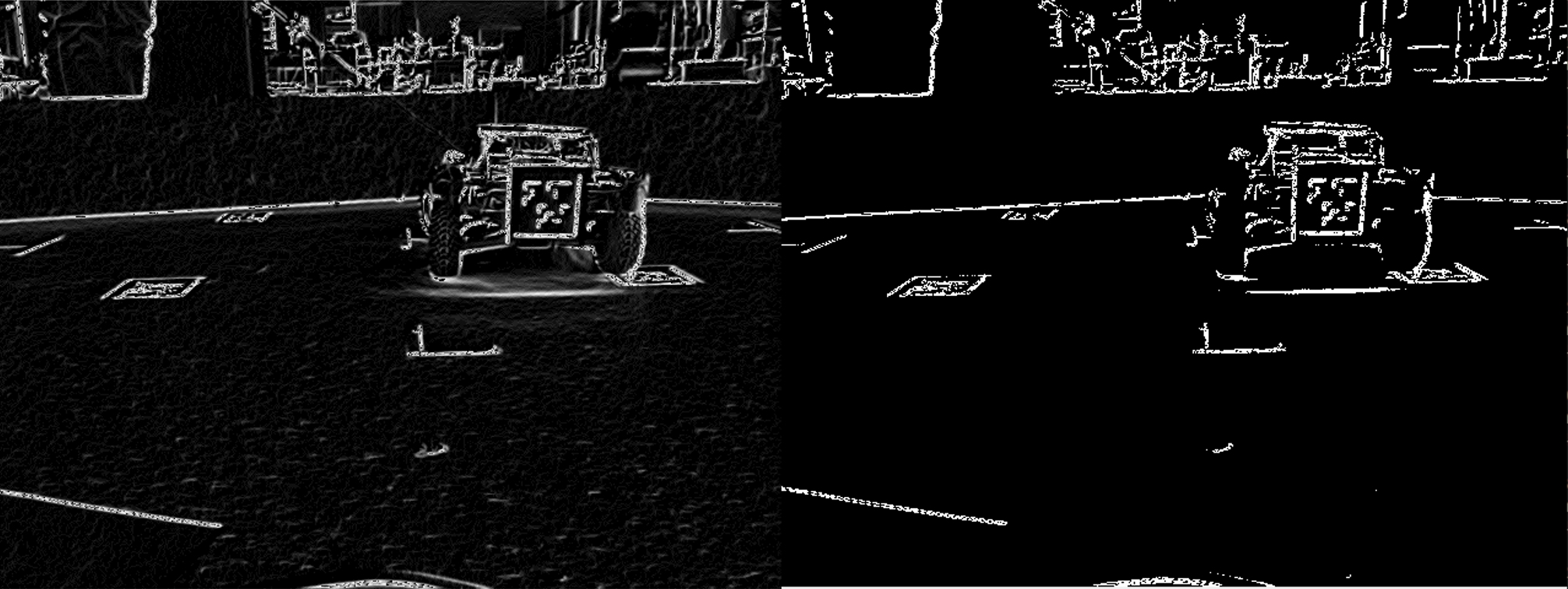
This method is based on using the gradients to estimate the position. First, the image from the camera is converted to grayscale. The grayscale image is filtered with a Gaussian kernel (cv2.GaussianBlur(image, (13, 13), 1)) as it improves the image stability when the camera is in motion. This image is then used for the gradient computation. The gradient is then thresholded by an experimentally set value (10). The result is shown in the following Figure, where the filtered grayscale gradient image is on the left and the thresholded image is on the right.

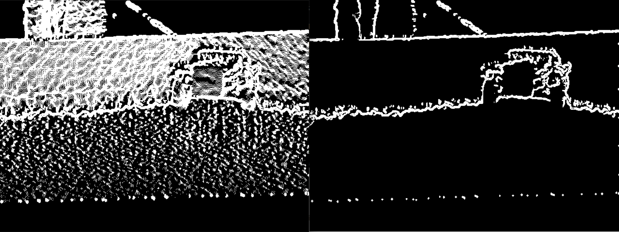
The depth image is provided by the LIDAR that is already transformed to the camera frame. The depth image is also filtered with Gaussian kernel (cv2.GaussianBlur(image, (13, 13), 1)) and then thresholded by an experimentally set value (8). The following Figure shows the filtered depth on the left and the thresholded image on the right.

After thresholding the individual gradients, the gradients are merged by a logical and into a final gradient. This way we can minimise the negative features of both camera and LIDAR. The camera image contains provides good resolution but contains too much detail. The LIDAR gradient has the ability to distinguish object edges without taking the color into account. However the LIDAR data contain a lot of noise resulting in unclear edges. By combining the gradients, we get a result that contains sharp edges and does not have the unnecessary detail of the grayscale gradient. The resulting image is in the following picture.

After merging the gradients, the centroid of the pixels. The computation of the centroid can be improved by rejecting outliers. The detected centroid is then transformed into the frame of planar LIDAR.
-
Advantages:
- Easy to implement.
- Fast processing.
- Detects the heading of the car.
-
Disadvantages:
- AprilTag must be visible.
- utilizes only the camera.
- the AprilTags will probably not be on the vehicles in the F1/10 competition.
A python library apriltag is used for the AprilTag detection. This library implements a function which detects the AprilTags with their IDs and estimates the relative rotation to the camera. This information is used to calculate the marker in the 2d view and to display the heading vector.
- LiDAR Technology: High-accuracy depth sensing from 0.25 to 9 meters.
- 2MP RGB Camera: High-quality color image capture.
-
Field of View (FoV):
- Depth: 70° × 55° (H × V).
- RGB: 70° × 43° (H × V).
- Frame Rate: Up to 30 fps for both depth and RGB capture.
- Measurement Range: Up to 10 meters.
- Wide Field of View (FoV): 270° horizontal scanning angle.
- High Scanning Speed: 25 milliseconds per scan (40 Hz).

- Objective: Use LIDAR for accurate distance measurements within the specified range.
- Method: Process the LIDAR data to detect objects and measure their distance from the vehicle.
- Objective: Determine the opponent vehicle's orientation and position.
- Method: Utilize image processing algorithms to analyze the camera data and extract relevant information about the opponent vehicle.
- Objective: Combine data from both LIDAR and camera systems for accurate position and orientation detection.
- Method: Implement sensor fusion techniques to integrate LIDAR distance measurements with camera orientation data, ensuring precise detection within the required parameters.