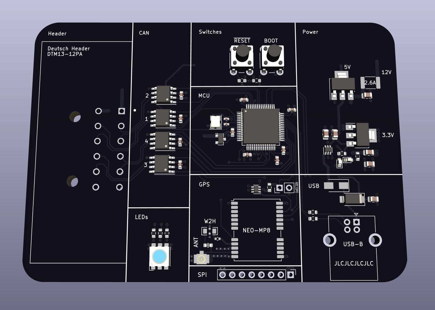
PCB and firmware for a USB to CAN interface, with support for 4 CAN transceivers and an optional NEO-MP8 GNSS module. The design is a reverse-engineering of comma.ai's Black Panda. It uses a modified version of the panda firmware/SDK.
For self-driving, it is better to buy a black panda from comma.ai. In addition to getting a more reliable product, you'll be supporting open-source software and a really smart group of people.
The design uses an automotive-grade Deutsch header, which eliminates the need for a switching relay. Feel free to replace this with something else. If you want to use "ODB-C" you'll need to use pins C0/C3 (inputs), C10/C11 (outputs).
To use the deutsch header, you'll need a crimper and some parts:
- 1 DTM13-12A or some variant of the header. This needs hand-soldered.
- 1 DTM06-12S, the male connector
- 1 WM-12S, a wedgelock
- 12 Crimpable Sockets
There are a few components that need purchased and hand-soldered to make the board work.
If you order the board as-is from JLCPCB, you can use it with or without GPS.
To use it with GPS, you'll need to hand-solder/install these parts:
- 1 NEO-MP8-2
- 1 W2H15C4738AT1A, a feedthrough capacitor for the GPS antenna.
- 1 Active GNSS Antenna. See Table 7 in the NEO-M8P guide for recommendations.
To use it without GPS, just jump the through-holes labeled NO_GPS. This will tell the firmware to ignore the GPS.
The board design is untested because of the chip shortage. Use at your own risk.
Credit to mickabrig7 for the original design and his guidance.
