-
Notifications
You must be signed in to change notification settings - Fork 6
Tutorial: Getting started with PSoC Creator | Blinking an LED
This tutorial will introduce you to the PSoC creator development environment by showing you how to blink an LED.
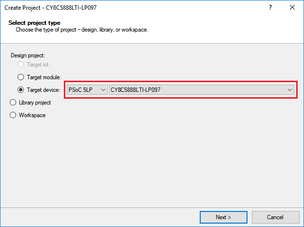
Start a new project in PSoC Creator by navigating to File -> New -> Project...
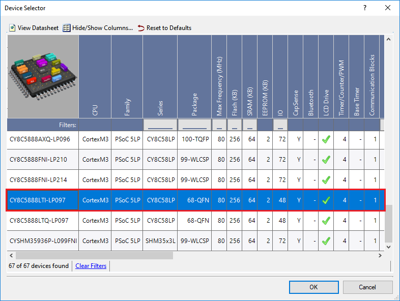
When selecting the target device, ensure that you select PSoC 5LP and CY8C5888LTI-LP097. If you forget this step, you can always change the device type later by navigating to Project -> Device Selector....
If the correct device is not selected by default, select it using the following list.
When prompted, choose the Empty schematic option when selecting a project template.
Name the workspace blink-led, with project name blink-led.
This project is very simple. You will only need to add two components.
First, open up TopDesign.cysch. This file contains the schematic for any analog and digital components that you add to your project.
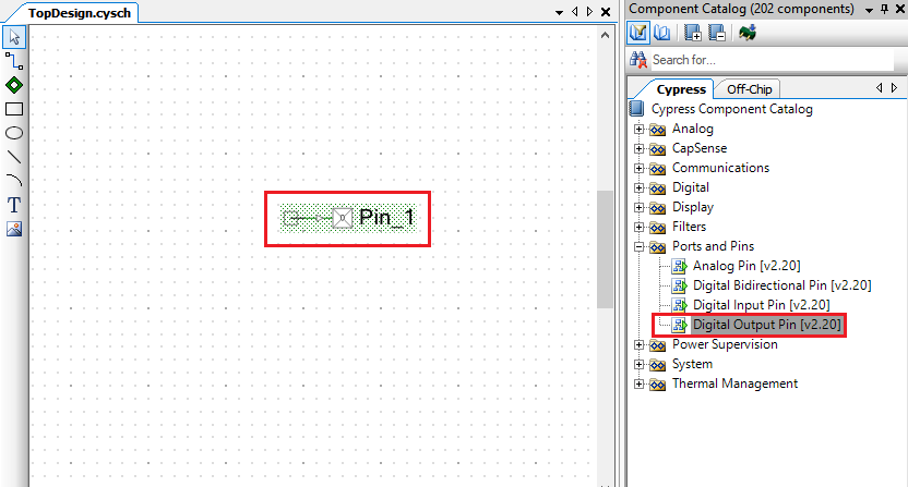
Locate the Digital Output Pin component under the Ports and Pins group in the Component Catalog. The Component Catalog is found to the right of your blank schematic sheet.
Drag the Digital Output Pin component from the Component Catalog onto the schematic. Use the zoom controls in the top toolbar to zoom if necessary.
Note: PSoC Creator has many useful components. You can right click a component to find example projects for that component, and to view the PDF of its datasheet, which describes all of its features and API calls in detail.
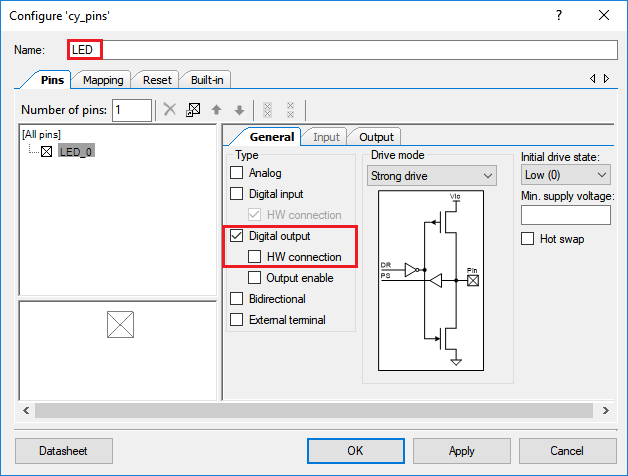
Right click (or double left click) on the Digital Output Pin and select Configure from the context menu. The Configure dialog allows you to edit default properties for that component.
Change the Name of the Digital Output Pin component to LED.
Note: Pay close attention to the case of names of the components. The name that you select for each component is used when the project is built to generate names for the associated application programmer’s interface (API) calls. The provided code will not work correctly if the names do not match exactly.
Because this pin will not be connected directly to any other PSoC components, uncheck the checkbox titled HW Connection.
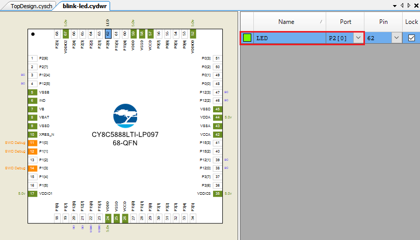
Before building the project, you must tell PSoC Creator which pin to use for the digital signal. On the perfect-cell board, the blue LED is mapped to pin P2[0].
Double click the blink-led.cydwr (Cypress design-wide resources) file in the Workspace Explorer.
Select the Pins tab at the bottom to show the pin configuration of the project. You will see a graphic of the PSoC chip with a description of the I/O pins and routing results.
Select P2[0] in the Port drop down menu.
We will now build the project to generate the API source code for the digital pin component.
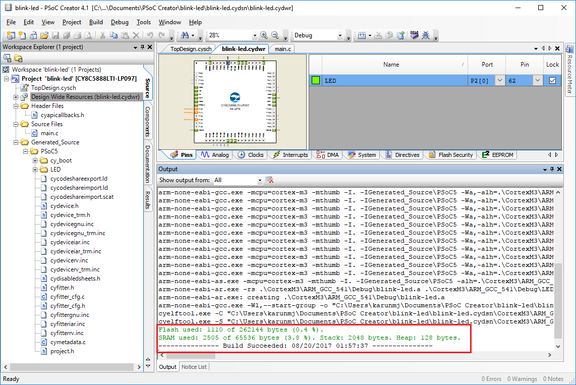
From the Build menu, select Build blink-led.
Note: If the build is successful it will say so in the output frame and there will be new generated source files in the Workspace Editor.
You are now ready to write firmware code. Building the project will generate an API for each of the pin components that you have just created.
PSoC Creator generates much of the code needed for this project. Open main.c by double clicking it under Source Files folder in the Workspace Explorer.
Note: Lines enclosed by /* and */ or which begin with // are comments. These are ignored by the processor but are great for explanations of code functions and to keep information useful to other people using the code. They are often colored green.
The code needed in the main.c file is quite concise for our simple project and is included below in its entirety. All we will do is run a never ending loop, which will turn the LED on and off for a specific duration of time. Please edit your main.c code, and add the code below.
#include <project.h>

int main(void)
{
    CyGlobalIntEnable; /* Enable global interrupts. */

    for(;;)
    {
        // Blink LED
        LED_Write(1u);
        CyDelay(200u);
        LED_Write(0u);

        // Wait 1 second
        CyDelay(1000u);
    }
}

/* [] END OF FILE */
The above code writes a logical 1 (high) value to our LED. Since the LED is connected to a digital pin, the operations are equivalent to flipping a pin high or low. The code then pauses for 200 milliseconds by calling the CyDelay() function, which is part of the standard PSoC library. The code then switches the state of the LED, waits an additional second, and keeps looping.
Note:
1,0,200and1000have a trailing 'u' to signify that they are unsigned meaning strictly positive integers.
-
To build your project again with this new code click
Build -> Build blink-led. -
To load the code onto your board, click
Debug -> Program. The program will compile and will load onto your board.
Congratulations! You just compiled your first PSoC program.
While you may be familiar with using LEDs for debugging purposes, the true power behind PSoC Creator lies in its advanced debugging interface. You can place breakpoints to halt the execution on of the code. During these breaks, you can also read the values of variables or memory locations. We will explore this feature and leave the reader to consult the PSoC Creator manual for advanced debugging functionalities.
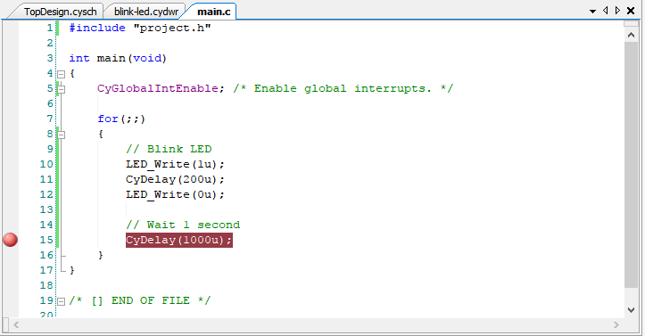
- Right click the line in the code that contains
CyDelay(1000u)andInsert Breakpoint.
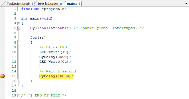
- Now use the Debug menu, or Debug toolbar, and click Debug to start the debugger. The debugger will start and pause on the line containing
CyGlobalIntEnable. This will also bring up the debugging toolbar:
- Click the green Play button in the debug toolbar. Every time you click play, the code will advance to the next breakpoint in the sequence. The yellow arrow marker on the left edge indicates the current location of the debugger in the code.
Note: Since we are in a
for(;;)loop, which continues indefinitely, the code will now just blink the LED each time the play button is pressed. Watch the LED on your board turn on and off as you keep clicking play.
Note: If we had declared any variables at this point, you would be able to hover over the variable name with your mouse to reveal its current value. This functionality will prove very useful for future tutorials.
- Feel free to play around some more with the debugger before continuing. You can click the blue square Stop button to exit the debugger.
If you have followed the tutorial to the letter and are not seeing any LED activity, it could be because you need to add a jumper pin to the board. A jumper pin needs added to the ST pins (next to the LEDs, see photo below).
