-
Notifications
You must be signed in to change notification settings - Fork 6
1. Hardware setup
- The easiest way to obtain an adapter is to modify a VAG-KKL cable, the cheaper the better.
- The cheapest cables often contain a Serial-to-USB chip (commonly WCH-CH340 or FTDI-FT232RL, which we don't need) and a 12V-5V logic level shifter, usually an LM339 comparator.
- In essence, the K-Line diagnostic protocol is a serial interface with 12V logic.
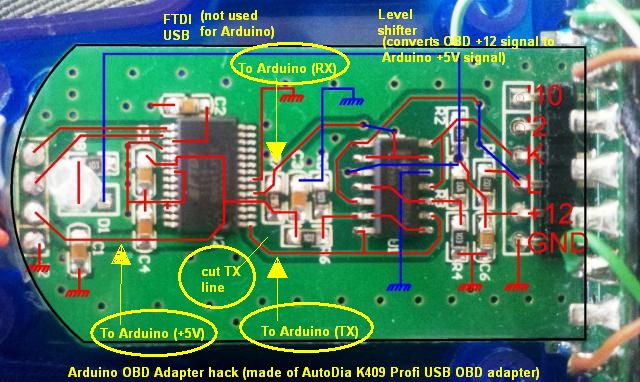
For simple cables, Alexander Grau's method is the most straightforward:

- The idea is to cut the connection between the level shifter and the USB chip on the TX (transmit line) so it doesn't interfere with our communications.
- The RX (receive line) can be left alone because it has no negative effects on communication.
- Both 5V and 12V power to the cable are necessary, read about power options here... and don't forget the ground!
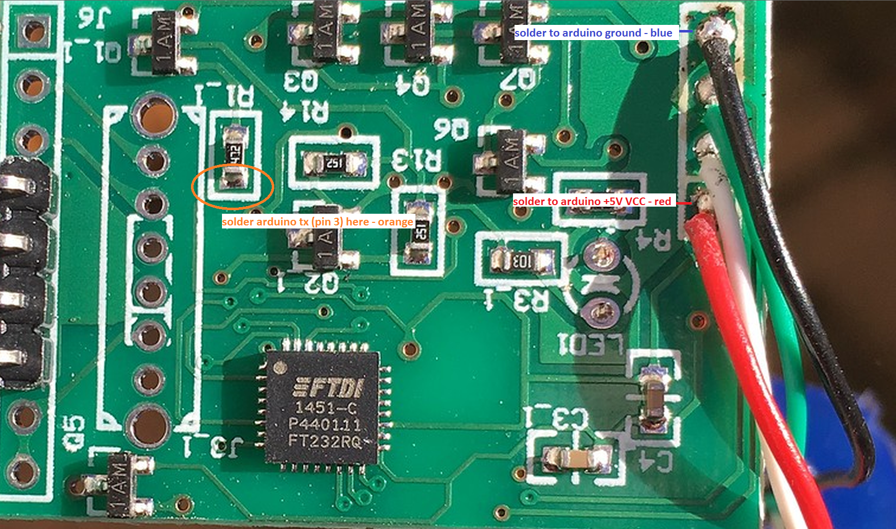
It's also possible with more complicated cables, as mkirbst shows on GitHub:


- The core idea is the same, but the author chose to cut both data lines.
- In such a cable where RX / TX lines control (or are controlled by) transistors, the wires for the Arduino need to be connected to the same trace that used to lead directly into the USB chip before cutting them.
Some fancier cables use a dedicated K-line driver (or even two), most commonly the L9637D. It is easy to find and buy, and the circuit is very simple. The only other component required is a 510 ohm (or thereabouts) pull-up resistor.

Although this IC's datasheet specifies a minimum supply voltage of 4.5V, I have found it works directly with the ESP32 at 3.3V (although I can't comment on reliability). I have not been able to get the modified cable to work on the ESP32 without an additional bi-directional level shifter, but your experiences may vary.
It is also possible to use a LIN transceiver IC (for example, the TJA1021T), since the LIN physical layer is derived from the K-line physical layer. These chips' datasheets also often describe them as "K-line / ISO9141 compatible".
My solution:
As I had one of the cheaper interfaces, I chose Alexander's method, but I also wanted to keep and reuse the USB cable for ease of connection to the Arduino.


- Like him, I cut the TX trace, but also the D+ and D- going from the USB cable to the Serial-USB converter chip.
- Next, I soldered the TX line (point on the cut trace, on the LM393's side) to where USB D- previously was (white wire from USB cable), and then the RX line (point on the circuit board connected as close as possible to the LM393 level shifter) to where D+ previously was (green wire from USB cable). Of course, it's your own choice whether RX and TX correspond to D- and D+ or vice-versa, but don't forget which way you chose.
- Warning, as with every modified USB cable that isn't actual USB anymore... please don't plug it into a computer after modifying!
For my testing, I have been using a VAG Instrument Cluster on my workbench, to which I have connected the adapter board directly to the K-Line.
-
In reality, this project will most likely be useful in logging values, installing custom displays or DIY scan tools.
-
A much neater approach would be including a small microcontroller + step-down voltage regulator inside the housing of the OBD2 connector.
-
One useful detail to consider is that all modules that communicate with this protocol are all connected to the same K-Line. Wherever you choose to connect it, either to the external diagnostic port or by tapping into the K-Line on the instrument cluster or the radio, you will be able to connect to any module inside the vehicle (provided they don't require to be woken up via the L-Line, like in some rare instances).
