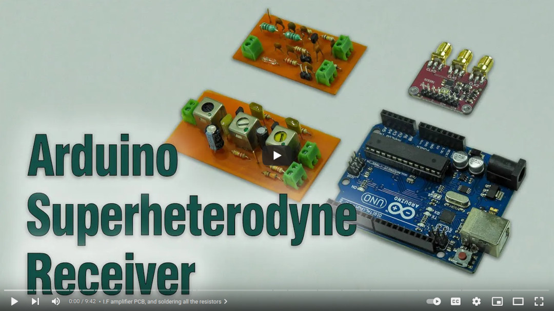
In this project, we will upgrade a traditional shortwave superheterodyne receiver with an Arduino base tuner. This tuner is capable of receiving shortwave broadcasts on 41m band and above.
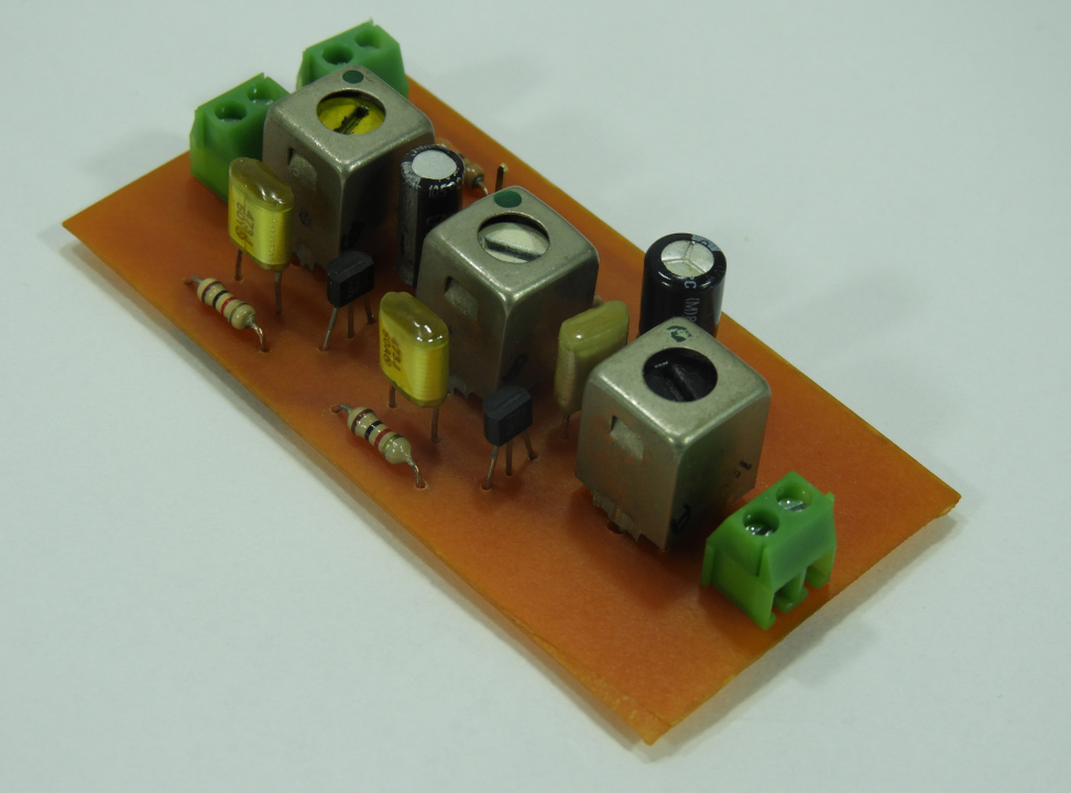
In this upgrade, we enhanced the local oscillator with Si5351 clock generator module and Arduino control circuit. Compared to the old design, this new receiver uses an improved version of an intermediate frequency amplifier with 3 I.F transformers.
In this new design, we divide this receiver into several blocks, which include, mixer with a detector, a local oscillator, and an I.F amplifier. The I.F amplifier builds into one PCB. The filter stage, mixer, and detector stages place in another PCB.
In this prototype build, the Si5351 clock generator drives using an Arduino Uno board. With the given sketch, the user can tune and switch the shortwave meter bands using a rotary encoder. The supplied sketch support clock generation from 5205kHz (tuner frequency : 4750kHz) to 16285kHz (tuner frequency : 15830kHz). If required, this range can further extend or reduce by modifying the Arduino source code. In the given source code, we use Etherkit's Si5351 library to control the clock generator module.
This receiver uses a conventional 455kHz I.F transformer kit in an intermediate frequency amplifier. We use a 2SC724 transistor for each filter stage. The value of this transistor is not critical and can be replaced with any suitable mid-frequency NPN transistor, for example, 2SC930, BF494, BC337, or 2SC829, etc.
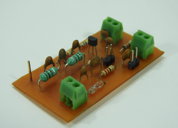
The 2nd PCB consists of a filter, mixer, and detector circuit. This mixer stage also uses the NPN low power transistor and can replace with any of the above transistors. The crucial component of the detector phase is the OA90 or 1N34 Germanium diode. It can also change with any suitable Germanium signal diode.
The front filter stage constructs using a pair of readymade 1µH inductors. The suggested supply voltage to this tuner is 6V to 9V.
All the design files of this project were released under the Creative Commons Attribution 4.0 International license. The Arduino sketch is released under the MIT License.


